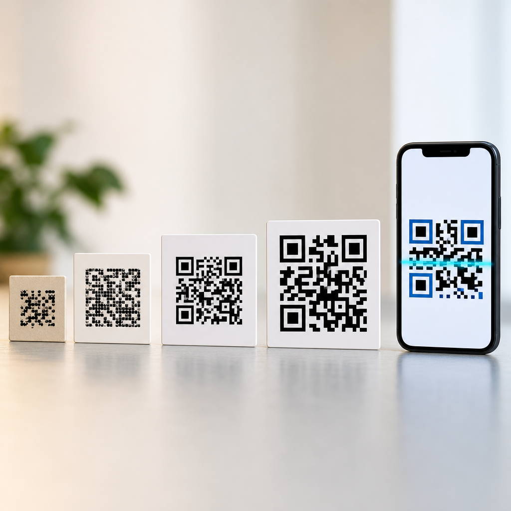
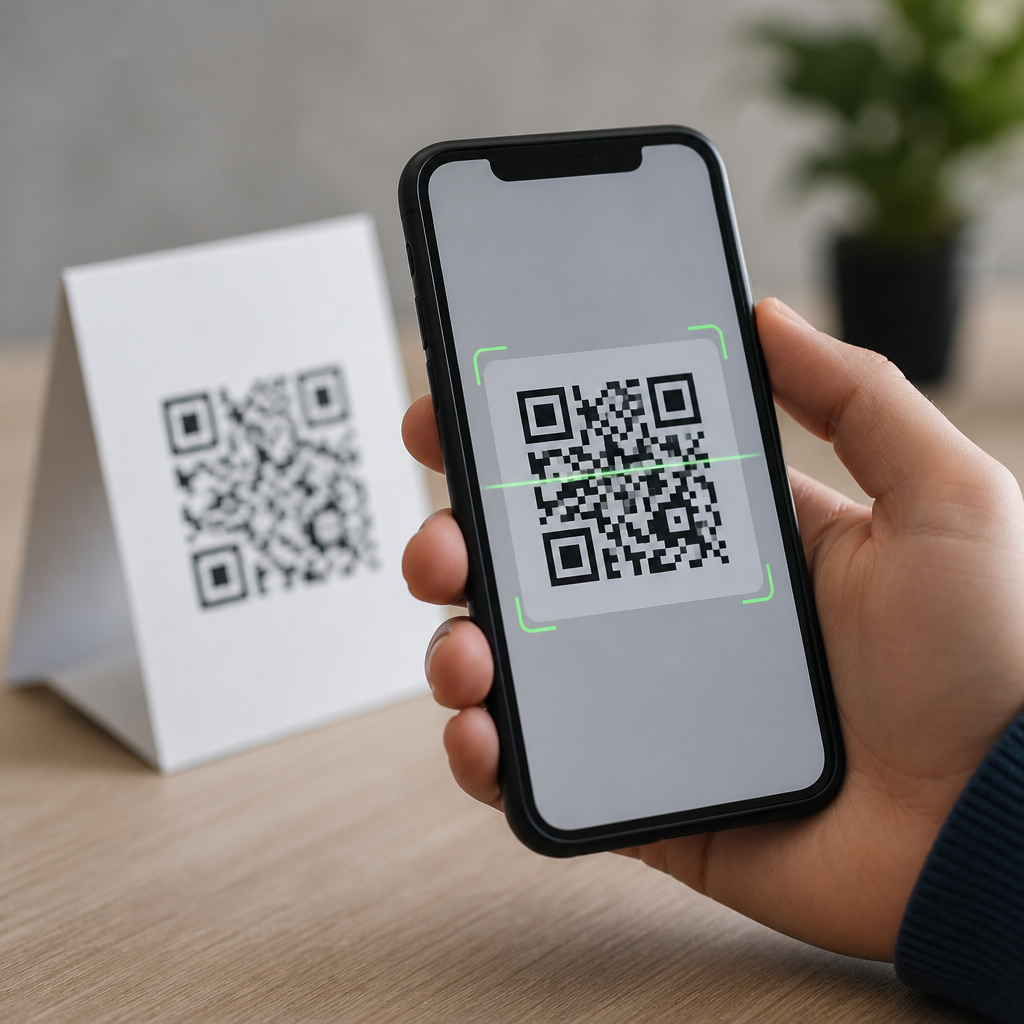
QR codes look simple on the surface, but reliable scanning depends on a carefully engineered layout of orientation and alignment patterns that help cameras find, rotate, and interpret the symbol in a fraction of a second. In practical terms, these patterns are the visual anchors inside a QR code: they tell a scanner where the code begins, how it is angled, how large each module is, and whether the printed image has warped across paper, packaging, or a phone screen. If you want to understand how QR codes work, these structures are the right place to start because they explain why one code scans instantly while another fails under glare, motion, or poor printing.
Orientation patterns are the large square markers placed in three corners of a standard QR code. They are often called finder patterns because they let imaging software locate the code within a wider scene. Alignment patterns are smaller target-like marks placed inside larger versions of the symbol to correct distortion. Together with timing patterns, the quiet zone, format information, masking, and error correction, they form the scanning system that makes QR technology dependable in retail, manufacturing, payments, ticketing, and marketing. I have tested QR codes on corrugated boxes, curved bottles, direct mail pieces, and digital displays, and the same lesson comes up every time: data matters, but the structural patterns determine whether the data can be read at all.
This matters because QR codes are no longer a novelty. They connect physical objects to digital content, support contactless workflows, and carry operational data in logistics and healthcare. A business can have the right landing page, tracking parameters, and creative design, yet still lose scans if the code’s structure is compromised. Learning how the orientation and alignment patterns work gives designers, marketers, print buyers, and product teams a better basis for choosing size, contrast, error correction level, and placement. It also creates a stronger foundation for every related topic in QR Code Basics and Education, from symbol versions to quiet zones, scanner behavior, and common scanning failures.
What orientation patterns do in a QR code
The three large squares in the top left, top right, and bottom left corners serve as the primary orientation system for a QR code. A scanner first looks for these high-contrast geometric features because they are distinctive and predictable. Each finder pattern is built from concentric dark and light modules in a 1:1:3:1:1 ratio along horizontal and vertical scan lines. That ratio is not decorative. It gives computer vision software a recognizable signature that remains detectable even when the code is scaled down, partially blurred, or viewed at an angle.
When a camera captures an image, decoding software typically converts the frame to grayscale, applies thresholding to separate dark and light regions, and searches for candidate shapes that match finder-pattern geometry. Once those three patterns are identified, the decoder can infer the QR code’s position, approximate size, and rotation. This is why a QR code can scan upside down or sideways with no problem: the finder patterns provide enough spatial reference for the algorithm to normalize orientation before decoding any payload data. In real deployments, this saves users from having to frame the symbol perfectly, which is essential for fast consumer scanning.
The absence of the fourth corner finder pattern is equally important. A scanner expects three large corner markers, not four, and this asymmetry helps distinguish QR codes from other square graphics. It also leaves room for format and version-related structures. In production testing, I have seen heavily stylized codes fail simply because decorative frames crowded the finder patterns or altered their contrast. The lesson is straightforward: those corner markers are not optional branding space. They are the first thing the scanner needs to trust.
How alignment patterns correct distortion
Alignment patterns are smaller square targets positioned within the body of the QR code, especially in larger symbol versions. Their job is to correct perspective errors and local distortion after the finder patterns establish global orientation. If a code is printed on a flexible label, wrapped around a bottle, or photographed from an angle, the grid of modules may no longer appear perfectly square. A scanner uses alignment patterns as additional checkpoints to map the warped image back to the intended module grid.
Unlike finder patterns, alignment patterns usually consist of a smaller dark-light-dark arrangement. Their placement depends on the QR code version. Version 1 symbols, the smallest standard QR codes at 21 by 21 modules, do not need alignment patterns because there is not enough area for distortion to accumulate significantly. As versions increase in size, more alignment patterns are added according to the ISO/IEC 18004 specification. This is one reason larger codes can remain readable despite carrying more data: the symbol includes more structural support to maintain decoding accuracy.
On a flat business card, alignment patterns may seem invisible in practical terms because scanning is easy. On a shipping drum or a sachet with heat-sealed wrinkles, they become critical. I have watched the same encoded data fail on a curved pouch in one layout and succeed in another simply because the symbol size increased enough to preserve alignment references and module integrity. That is a useful reminder that scan reliability is physical as well as digital.
How orientation and alignment work together during scanning
A QR scan is a sequence of detection and correction steps, not a single read. First, the camera captures the scene. Then the decoder identifies finder patterns, estimates the symbol boundary, and calculates rotation. Next, timing patterns and alignment patterns help define the exact spacing of modules across the symbol. After that, the software samples each module position, reads format information, removes the data mask, applies Reed-Solomon error correction, and reconstructs the stored message. Orientation patterns start the process; alignment patterns refine it so the data can be sampled correctly.
This division of labor explains why a code can still fail even when the three big corner squares look intact. If the center area is stretched, glossy, low contrast, or poorly printed, the scanner may detect the code but misread the module grid. In practical troubleshooting, that distinction matters. Detection problems usually point to finder pattern interference, missing quiet zone, extreme blur, or weak contrast. Decoding problems often point to distortion, insufficient module size, damage in the data area, or aggressive design customizations that disrupt alignment references.
Modern smartphone decoders, such as those built into iOS and Android camera apps, are excellent at handling moderate skew and uneven lighting. Even so, they are constrained by the physical pattern map the code provides. Better software improves tolerance; it does not remove the need for correct symbol structure. That is why standards-based generation and print quality control still matter.
Key QR code structures that support these patterns
Orientation and alignment patterns do not work in isolation. They rely on several neighboring structures that complete the symbol’s geometry and metadata. Understanding these elements is essential for anyone learning how QR codes work as a complete system.
| Structure | What it does | Why it matters for scanning |
|---|---|---|
| Quiet zone | Blank margin around the QR code, typically four modules wide | Separates the symbol from surrounding graphics so finder patterns can be detected cleanly |
| Finder patterns | Three large corner markers | Enable rapid detection, orientation, and scale estimation |
| Timing patterns | Alternating dark and light modules between finder patterns | Define row and column spacing so the decoder can sample the grid accurately |
| Alignment patterns | Smaller internal targets in larger versions | Correct perspective distortion and local warping |
| Format information | Bits describing error correction level and mask pattern | Lets the decoder interpret the symbol correctly before reading data |
| Version information | Version metadata in larger symbols | Tells the decoder the symbol size and expected structure |
| Data and error correction codewords | Encoded payload plus recovery data | Allow damaged or partially obscured codes to remain readable |
The timing patterns deserve special attention because they bridge the finder patterns and alignment patterns. Running horizontally and vertically between the main corner markers, they alternate dark and light modules in a regular sequence. Once the scanner knows where the corners are, timing patterns reveal how far apart the module centers should be. Without this spacing reference, the software could detect the code but still sample the wrong cells, especially in low-resolution captures.
Why print quality, size, and placement affect scan performance
Structural patterns can only help if they remain physically clear. The most common reasons QR codes fail in the field are not exotic algorithm issues; they are basic production mistakes. If modules fill in from ink gain, if white spaces close up on porous stock, if glossy laminate creates specular highlights, or if the code is printed too small for the expected scan distance, the finder and alignment patterns lose clarity. A scanner cannot recover geometry that was never preserved in the printed symbol.
Size should be tied to use case. A simple rule used in print is that minimum scan distance is often about ten times the code width, though camera quality and environment can shift that. For packaging viewed at arm’s length, a code around 0.8 to 1.2 inches wide may work well if contrast is strong and data density is modest. For posters scanned from farther away, the symbol must grow accordingly. More encoded characters increase the version, which reduces module size unless the overall printed code becomes larger. That tradeoff is central to real-world QR planning.
Placement matters too. Avoid folds, seams, bottle shoulders, tear notches, and highly curved areas whenever possible. On cylindrical containers, rotating the code so the scan lines encounter less curvature can improve results. On digital screens, leave generous quiet zone and avoid placing codes over animated backgrounds. In campaign audits, I have found that moving a code two inches away from a reflective edge can improve scan success more than changing the generator or raising the error correction level.
Common design mistakes that interfere with orientation and alignment
Customization is often where good QR codes go bad. Brand teams want rounded modules, embedded logos, inverted colors, gradients, and decorative frames. Some of these changes are possible, but each one consumes part of the symbol’s tolerance budget. The first rule is simple: never alter the basic geometry of the finder patterns or cover alignment patterns. If the scanner cannot trust those anchors, the rest of the code becomes irrelevant.
Low contrast is another frequent problem. Dark gray on medium gray may look refined in a style guide, but cameras need strong luminance separation. Black on white remains the most reliable combination. Reversed light-on-dark codes can work in some environments, yet they are less universally dependable because thresholding behavior varies across scanners. Color combinations that appear distinct to the eye can compress into similar grayscale values, which is what many decoders use during detection.
Overstuffing data is also a design mistake, even though it seems unrelated to aesthetics. A long URL with tracking parameters increases symbol density, creating smaller modules that are harder to print and scan. Using a short redirect URL or dynamic QR code platform often yields a less dense, more robust symbol. In practice, simplifying the payload is one of the fastest ways to improve scan reliability without changing the message destination.
Best practices for building a reliable QR code hub strategy
Because this page serves as a hub for how QR codes work, the main takeaway is that scanning reliability begins with structure. Start with standards-compliant generation from reputable tools such as ZXing-based generators, QRCode Monkey, or enterprise platforms that expose error correction settings and output vector files. Keep the quiet zone intact. Use adequate size for the intended distance. Preserve high contrast. Test on the real substrate and in the real lighting conditions where the code will live. If you customize, do it conservatively and verify performance across multiple devices.
For educational planning, connect this topic to the rest of QR Code Basics and Education. Readers who understand orientation and alignment patterns are ready to learn about quiet zones, QR code versions, error correction levels, static versus dynamic QR codes, print testing, and scan analytics. Those topics are not separate from this one; they extend it. Every successful QR implementation depends on the scanner’s ability to locate the code, map the module grid, and recover the payload under imperfect conditions.
The essential point is clear: orientation patterns tell a scanner where the QR code is and how it is rotated, while alignment patterns help the scanner correct distortion so each module is read from the right place. Together they are the reason QR codes can work on packaging, labels, signs, and screens despite motion, skew, and surface irregularities. If you want better scan rates, protect these patterns first, then optimize size, contrast, payload length, and placement. Use this hub as your starting point, and review the related QR Code Basics articles before creating your next code.
Frequently Asked Questions
What are orientation and alignment patterns in a QR code?
Orientation and alignment patterns are two of the core structural features that make a QR code readable under real-world conditions. The orientation patterns are the three large square markers placed in three corners of the symbol. They are often called finder patterns because they help a scanner quickly locate the code within a larger image. When a camera sees those three distinctive squares, it can immediately separate the QR code from the background and determine which way the symbol is facing.
Alignment patterns serve a different but equally important purpose. These are smaller square targets placed inside the QR code, usually away from the corners, and they help the scanner correct for distortion. If a QR code is printed on curved packaging, viewed at an angle, or slightly stretched by the camera perspective, the alignment patterns give the decoding software extra reference points to map the grid accurately. In simple terms, the finder patterns tell the scanner where the code is and how it is rotated, while the alignment patterns help it understand the shape and spacing of the internal data grid so the code can still be read quickly and accurately.
How do the three large corner squares help a QR code scanner work so fast?
The three large corner squares are designed to stand out immediately to image-processing software. Their bold, high-contrast square-within-a-square appearance is visually distinctive, so scanning systems can detect them much faster than trying to interpret the entire QR code at once. Once the scanner identifies those three markers, it can estimate the code’s position in the frame, its approximate size, and its rotation. That means the software does not need to guess where the QR code begins or which direction it should be read.
This is a major reason QR codes scan so quickly, even from imperfect photos. A user might hold a phone at an angle, move slightly during capture, or present a code against a busy background. The finder patterns act as anchors that let the scanner lock onto the symbol almost instantly. From there, the software can establish the boundaries of the QR code, normalize its orientation, and begin measuring the rows and columns of modules. Without these corner markers, scanning would be slower, less reliable, and far more sensitive to camera angle, motion, and framing.
Why are alignment patterns necessary if a QR code already has finder patterns?
Finder patterns and alignment patterns solve different problems. Finder patterns are excellent for helping a scanner locate the QR code and determine its orientation, but they do not provide enough information by themselves to fully correct distortions across the entire surface of the symbol. In ideal conditions, a flat, perfectly printed QR code viewed straight on might be decoded with minimal correction. In practice, though, QR codes are often printed on labels, bottles, boxes, posters, receipts, and screens where warping, skew, and perspective distortion are common.
Alignment patterns give the scanner additional checkpoints inside the symbol so it can verify that the module grid remains properly spaced across the code. This is especially important in larger QR codes that contain more data and therefore have more modules. Even small geometric errors can shift the reading of those modules and cause decoding failures. By referencing alignment patterns, the scanner can compensate for bending, stretching, or uneven imaging and reconstruct the intended grid with much greater precision. In short, finder patterns get the scanner oriented, while alignment patterns help it stay accurate across the full symbol.
How do these patterns help QR codes scan on curved surfaces, damaged prints, or angled photos?
QR codes are rarely encountered in perfect laboratory conditions. They may be wrapped around a bottle, printed on textured cardboard, partially smudged, photographed under glare, or captured from an off-center angle. Orientation and alignment patterns are critical because they give decoding software known geometric references that remain useful even when the overall image is imperfect. The scanner first uses the finder patterns to locate the symbol and estimate its angle. It then uses alignment patterns, along with timing and grid information, to model how the code has been distorted.
That correction process allows the software to transform a warped or tilted image into a more regular grid for decoding. If one area of the QR code is stretched due to curvature or perspective, the alignment pattern helps the scanner understand that the modules in that region are not actually larger data cells but simply visually distorted ones. Combined with error correction built into the QR code standard, this structure makes the format highly resilient. The result is that a QR code can often still scan successfully even when it is not flat, not centered, and not perfectly printed, which is a major reason the technology works so well in everyday use.
Do larger or more complex QR codes rely more heavily on alignment patterns?
Yes. As a QR code stores more information, it typically becomes denser and may use a larger symbol version with more modules across its width and height. In those larger versions, maintaining accurate module placement becomes more challenging because small visual distortions can create larger reading errors over distance. That is why bigger QR codes include more alignment patterns. These extra reference points help the scanner confirm the geometry of the symbol in multiple areas rather than relying only on the outer corners.
This matters because decoding is fundamentally a grid-reading problem. The scanner must determine exactly where each tiny black or white module begins and ends. In a dense code, even a slight shift can cause the software to sample the wrong cells and misread the data. Additional alignment patterns reduce that risk by giving the decoder more internal anchors for correcting local distortion. So while all QR codes benefit from structured orientation, larger and more data-heavy codes depend even more on alignment support to maintain fast, reliable scanning performance across different print materials, camera qualities, and viewing angles.